Volumetric Distorted Arrow
Moving on from the arrow created in tutorial Making the most of Node Expressions we can add thickness and render as a volume. This opens up many possibilities as the volume can then be distorted in interesting ways to allow effects that cannot be easily achieved using meshes alone, in the same way as a volume captured from a mesh using Smoke2EXR can be distorted.
Requirements
Smoke2EXR add-on (required)

The Volume
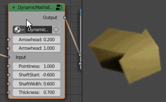
Starting with the 'arrow' example in the previous tutorial, in order to convert the mesh into a volume we just need to add an additional constraint based on the Z coordinate - ie, any point will be considered to be within the volume if it is within the 'arrow' in to dimensions (X and Y) and also close enough to the plane Z = 0. This can be achieved in the same way as how we determined the distance from Y=0 for the symetry of the arrow - ie, 'abs(Input[z]) < Thickness'. The expression from the end of the previous tutorial now becomes the following (note the changes in bold) :
outputs(Output)
YDist = abs(Input[y])
ArrowheadX = Input[x] - ArrowheadStart{0.2}
Shaft = and( Input[x]>ShaftStart{-0.6}, Input[x]<=ArrowheadStart, YDist < ShaftWidth{0.6}/2 )
Head = and( Input[x]>ArrowheadStart, YDist < (ArrowheadWidth{1}/2-ArrowheadX/Pointiness{1}) )
Output = and(or(Shaft, Head), abs(Input[z]) <= Thickness{0.7}/2)
The above changes change the Output line such that the output is only ever '1' (ie, within the volume) if the point is within the arrow AND the distance to the Z=0 plane is less than half the Thickness. The default value ('{0.7}') ensures the new input is created with a non-zero value - otherwise the volume with have zero thickness and will become invisible.
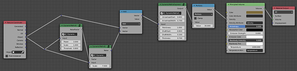
In order to render this as a volume you'll need to make a few changes to the nodes to replace the surface shader with a Volume shader and add a Maths 'Multiply' node to allow you to control the density (a density of 1 will be quite wispy, while, say, 30 will produce a much more solid volume). Change the nodes to something like the following (you can use a Volumetric Scatter in place of the Principled Volume if using an earlier version of Blender) :

Note the Maths node set to Multiply by 30 to increase the density and also that the Principled Volume is connected to the Volume socket of the Material Output, rather than the Surface socket.
Rendering with Cycles
When rendering sharp-edged volumetrics using the Cycles render engine, the default settings can produce "reasonable" results, although it can appear quite banded due to the low resolution of the default settings. This can be greatly improved with a few minot changes - although this will also drastically affect render times - so care needs to be taken to only make sufficient changes to get acceptable render results.
-
Start by increasing the Light Paths 'Volume' setting for Max Bounces. This controls how many times a scattered ray is permitted to bounce within a volume before it is considered 'lost'. With the default setting of zero, any scattered rays that happen to bounce into the volume will instantly be lost, resulting in a fraction of the light hitting the volume leaving the surface and making the surface darker. By increasing the number of Max Bounces there is greater chance of each ray escaping the surface with minimal additional overhead to the render. Values over about 3 or 4 will not generally have much of an effect - unless you have a low-ish density and are looking to create a sub-surface scatter effect.
-
Next, try adjusting the 'Step Size'. This setting effects how small the step through the volume should be before the render engine checks for scatter collisions with the density at that point. Smaller step sizes improve the resolution of the volumetric but at great expense of render time. This is the setting that can have the most significant effect on render quality - and also significantly increase render times!!
-
A closely related option is Max Steps - this option limits the maximum number of steps through a volume. If the Step Size is suitably small (so you would orinarily have lots of small steps through the volume) then this setting can be used to limit the number of steps.
-
You may also want to change the color of the volume shader to something more interesting than the default "pure grey" and move the lights closer and position them to bring out the volumetric form.

Default settings - notice the banding due to the large Step Size

Altered volumetric settings - adding more render 'samples' will improve the render further
Rendering with Eevee
Eevee default render settings are really not suited for small scale high density volumetrics, but more intended for general fog effects - the default settings rendering the same arrow produce the following with the default Eevee volumetric settings :

In order to get sharp volumetric renders in Eevee you need to make the following changes :
-
Ensure Volumetrics is actually enabled (in pre-release versions of Eevee you had to specifically enable a checkbox in the Render properties to enable Volume rendering (it's automatically enabled for you now and this is no longer necessary).
-
Adjust the Volumetrics 'End' as close to the maximum distance of your volume as possible, within obviously cutting off your volume. eg, if the volume is within a 2x2x2 cube and the cube is 3 Blender Units from the camera/viewpoint then setting it to 6 should encompass you volume Note : This is required as Eevee approximates your volume by building an internal buffer of grid cells, wit the cells representing the volume over the entire range (Start to End). With a wide range those cells are very coarse and so the volume is inaccurate. By limiting the range to the volume depth only, you can get much sharper rendering of the volume.
-
Adjust the Volumetrics 'Start' to be as close to the start of your volume (from the camera/viewpoint as possible - for the same reasons as for 'End'.
-
Reduce the Tile Size - ideally right down to '2px'. This increases the resolution of the volume (at the expense of memory/render time).
-
Enable Volumertric Shadows and increase the Shadow Samples (maximum = 128 samples) (this allows the volume to cast shadows - including onto itself - which greatly improves realism).
-
Place your lights close to the volume and potentially reduce their size - this improves the Volumetric Shadows, bringing out the detail of your volume.
-
Change the volume shader color to an off-white colour - rather than the default pure grey.
This can produce the following results (rendered in real time!) :
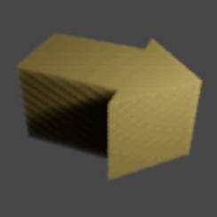
Note that this isn't as cleanly rendered as Cycles - it never will be, due to the different render methods - but is capable of being rendered in very near realtime.
The quality can be further improved by rendering the final image at increased resolution and then scaling back down to the original required resolution (ie, render at 200% and then scale back down to 100%). However, this will increase render times and memory overheads for the render.
It is sometimes desirable to use Eevee to render in the viewport for instant viewing and manipulation, then switch to Cycles for the final render.
Since the arrow is generated procedurally and rendered in near-realtime, we can make changes to the node group properties and instantly see the results :
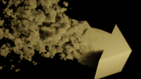
Distortion
Since we now have a volumetric arrow, we might as well do something with it that we can't do with a mesh - add procedural distortion to that it appears to be forming from fluid. This can be relatively simply achived by distorting the Input coordinates - increasing the distortion as we move further away from some threshold. This can be achieved with the following expression :
# Expression to vary the noise over the volume - so it increases to
# one side of a threshold
NoiseFactor = (max(Threshold - Input[x], 0) * Scale{1}) ** Power{3}
To explain, this takes the Input 'X' coordinate, subtracts the Threshold and uses a 'max' with zero to cut off any negative values - this will result in a value that is zero to one side of the threshold and linearly increases the further the point moves to the other side of the threshold. The Scale and Power factors allow the rate of increase of the noise to be adjusted.
Paste the above into a new text block named 'graduatenoise' and create the node group by adding the expression 'TEXT:graduatenoise'.
To generate the actual noise using this NoiseFactor, we can use one of the preset expressions in Node Expressions for generating variable noise - simply add the expression and select Preset 'Variable Distort (Noise)'. This is actually implemented as the following expression :
# Variable Distort(Noise) : Variable strength noise (centred on 0,0,0)
Noise[] = vmult(vsub(noise(Input[], Scale), 0.5), Factor)
This expression uses some vector maths to adjust the output of a Noise texture by subtracting 0.5 (so it's centred around 0.0, rather than 0.5) and then scale it by the incoming factor (making it variable).
These new groups can be combined with our existing volumetric arrow as follows :
You can then adjust the relevant group variables to produce a result similar to the following (rendered using Eevee) :

Taking this a step further, you can animate an offset of the Noise (you can achieve this by simply adding a Mapping node before the Input of the Noise group and then animating the X Location offset).