
Making the most of Node Expressions
To really unleash the power of Node Expressions you really need to combine it with a text block. This allows you to enter the expression as more than just a single line of text (which is all you can do in the 'Lite' version of the add-on) and opens up many additional features.
Workspace
In order to avoid having to continually swap between views it's useful to take a moment to arrange your workspace so you have easy access to a 3D View window (so you can see the results of your efforts), a Text Editor window (so you can edit the text) and at least one Node Editor window (so you can easily trigger updates to the node group - it can also be useful to have a second Node Editor window as this allows you to simultaneously work on both inside (to trigger updates) and outside (to adjust values and connections) of the node group.
In Blender 2.8 the 'Shading' preset workspace is a good starting point - just change the File Browser to a Text Editor and the Image Editor to a Shader Editor as shown :

Text Editing
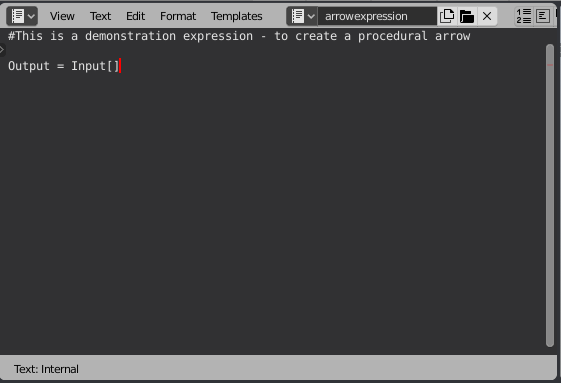
In the Text Editor window, create a new text block by clicking 'New' and give it a suitable name. In this example, I'll create a simple function to convert the input coordinates into a procedural 'arrow' - so I'll call mine simply 'arrowexpression'. I want the node to accept an input vector and produce an output that is either 0.0 for points outside the arrow and 1.0 for points within the arrow so it will have. For now I'll just create it with an expression of 'Output = Input[]' so we can get a simple node set up for the demonstration. Note that in the text editor you can add blank lines and comments (by prefixing a line with '#') to improve the readability of your expression :
You can now add the expression to the node tree by selecting Add/Maths Expression. In order to use the text block you use the 'TEXT:' prefix to indicate the text block to use. In my case I have named the text block 'arrowexpression' so entered the expression as 'TEXT:arrowexpression'.

You should now have a new node in the node editor :

You can now arrange the available windows such that one of the node editors shows an external view of the node and the other shows the internal view (by clicking on the icon at the top-right corner of the node) to have a workspace similar to the following :

Note the 'Update expression from Text Block' button within the control node within the expression group - this is available whenever you're using a text block as the source of the expression. Simply amending the text in the text block and then clicking the 'Update...' button will automatically refresh the node group, making it easy to try different expressions.
Also notice the nodes that the add-on has created for you from your text - there's a Group Input with a Vector socket for 'Input' and a Group Output with an output named 'Output' - and input is connected directly to output - ie, to implement the expression 'Output = Input'. Ignore the Separate XYZ node for now - that's simply created since we've indicated that Input is a Vector by including the empty square bracket suffix.
All that's left is to connect the node to provide an input and to do something with the output and we can start writing the actual expression - so connect a Texture Coordinate node - in this case I'll be using Object coordinates (since it has its origin in the centr of the mesh - this will be useful for the centreline of our arrow) - and connect the output to the shader.

An Arrow
As mentioned earlier, the aim of this exercise is to create a procedural arrow - something like this :

There are a number of things to note about this shape.
-
It's vertically symetrical along the centreline
-
It's made up of 3 sections
-
The part to the left of the 'shaft' of the arrow - before the start of the arrow.
-
The 'shaft' has a constant width up to the start of the 'head'
-
The 'head' starts at a different width to the 'head' and diminishes to zero
-
Since we're using Object coordinates we can use Y=0 for the centre line - so to determine the distance from the centreline we can simply use the Y-coordinate. We can use the 'abs' function ("absolute") to ignore the sign since we don't care which side of the centreline the point is at (since our shape is symetrical). We want the output to be '1' when we're close to the line and 0 when we're far from the line - so we can use a 'Less Than' operation for that.
Edit the expressions to the following :
YDist = abs(Input[y])
Output = YDist < 0.25
This defines YDist as being the distance away from the Y-axis by taking the 'Y' element of the input vector 'Input' and passing it through the 'abs(...)' function to ignore the sign. YDist is compared with 0.25 to give 'true' (1.0 - or white) when the distance is less than a constant value (0.25).
Once you've amended the expression, click the 'Update...' button to update the node group. You should now have something like the following :

So far so good, but what if we want to be able to change how wide the arrow shaft will be? We want to be able to specify the width and perhaps adjust it by changing the input to the group. This can be achieved by simply replacing the '0.25' with a name - eg, "Width". Since we want the input variable to control the total width of the shaft but it's actually measuring the distance from the axis (so is on both sides of the axis) we need to measure using half the width by dividing by two - so the expression is as shown below :

Now, the width of the band can be controlled simply by varying the 'Width' input :
<animated - varying the width>
The Arrowhead
For the arrowhead we need to vary the width of the band based on the X coordinate - with its maximum being at the start of the arrowhead and the width diminishing towards the point. Consider the following expression :
YDist = abs(Input[y])
ArrowheadX = Input[x] - ArrowheadStart
Output = and(YDist < (ArrowheadWidth - ArrowheadX), Input[x]>ArrowheadStart)
Here we're calculating the distance from the y-axis as before (_YDist), followed by calculating how far along the arrowhead we are (_ArrowheadX). We can then calculate the 'width' of the arrowhead at that point by subtracting one from the other (so that the width diminishes the further along the arrowhead we travel, finally ending at a point). Varying ArrowheadWidth and ArrowheadStart will move and scale the arrowhead.
Notice the use of the 'and(...)' function - this takes multiple exressions and combines them so that that all must be 'true' to give a 'true' answer - in this case we only want to draw the arrowhead if the X-coordinate is greater than the ArrowheadStart.
We've now almost got everything we need to create the final arrow - we just need to combine the shaft with the arrowhead and we can use the 'or(...)' function for this (the or function returns 'true' if any of the inputs are true) - so we have :
YDist = abs(Input[y])
ArrowheadX = Input[x] - ArrowheadStart
Shaft = and( Input[x]>ShaftStart, Input[x]<=ArrowheadStart, YDist < ShaftWidth/2 )
Head = and( Input[x]>ArrowheadStart, YDist < (ArrowheadWidth/2-ArrowheadX) )
Output = or(Shaft, Head)
To explain, 'YDist' represents the distance from the Y-axis while 'ArrowheadX' is calculated as the distance along the arrowhead. 'Shaft' calculates whether a point is within the arrow shaft (ie, the point must be after the start of the shaft AND before the start of the arrowhead AND suitably close to the Y-axis), Head calculates whether the point is within the arrowhead (ie, after the start of the arrowhead AND closer to the axis than half the width minus a factor to taper it to a point). Finally, Output combines Shaft and Head, outputting 'true' if the point is on the Shaft OR the Head (Note: This could actually have been written as 'Output = Shaft + Head' to combine the two - and this is more intuitive. However, this will only work if the two regions do not overlap (which they don't in this case) - so it's safer to use 'or'. However, another alternative is to use 'Output = clip(Shaft + Head)' as that will be limited to '1' even if the regions overlap).
This produces the following node and results :

Tidying Up
The resultant node group includes the outputs of all the intermediate sub-expressions of the calculation - ie, YDist, ArrowheadX, Shaft, Head. If we're not interested in having access to those outputs then they can be hidden in one of two ways.
Firstly, any variables that start with an underscore character ('_') are automatically classed as 'internal' variables and are therefore hidden from the inputs and outputs of the group - so you could rename YDist throughout the expression to _YDist and it would no longer be available as an output to the group. This is a good way of making it clear in your expression that a variable is intended for internal use only - but does require you to amend your expression to 'hide' them.
Another way is to include an 'outputs(....)' function in your expression. This should be included before you use the variables and any variable not listed as an 'output' will be automatically hidden.
We can also add defaults to the various input variables to the expression. When creating a new node, these defaults will be used as initial values for those inputs. You define defaults by specifying it in a {....} suffix to a variable - so, in our case, we could change the expressions to the following to specify a single 'Output' and to set the defaults on each of the inputs :
outputs(Output)
YDist = abs(Input[y])
ArrowheadX = Input[x] - ArrowheadStart{0.2}
Shaft = and( Input[x]>ShaftStart{-0.6}, Input[x]<=ArrowheadStart, YDist < ShaftWidth{0.6}/2 )
Head = and( Input[x]>ArrowheadStart, YDist < (ArrowheadWidth{1}/2-ArrowheadX/Pointiness{1}) )
Output = or(Shaft, Head)
Note also the added bonus of a 'Pointiness' variable in the calculation of the head to allow the sharpness of the arrowhead to be controlled (larger values extend the arrowhead into a sharper point while smaller values shorten it).
