Tutorial : Converting a Mesh into a Volume
To produce some effects it can be useful to be able to generate a volumetric in a very specific shape. This *can* be done mathematically (such as generating a volumetric arrow) - but that can become quite complicated for more detailed shapes - or an alternative is to convert the volume enclosed by a mesh directly into a volume. The Smoke2EXR add-on can be used for this - by using a smoke simulation to fill the volume with smoke and then convert that smoke into an EXR image that can be used in a volumetric shader. Once you have captured the volume you can manipulate it to produce some interesting effects.
Requirements
Smoke2EXR add-on (required)
Node Expressions add-on (recommended)
Smoke Simulation
The first stage in capturing the volume is to ensure your mesh is manifold - this means that it completely encloses a volume without any overlaps or gaps. For this tutorial I'll be using the standard Suzanne mesh - but, unfortunately this isn't actually manifold due to the eyes being separate and overlapping - so a little work is required first to enclose the eye sockets properly. Note that this stage can sometimes be omitted (smoke simulations *can* produce valid volume results from non-manifold meshes but non-manifold meshes may produce occasional artifacts).

Smoke Domain
Create a smoke domain around your mesh and set the Resolution of the domain to the desired level of detail for your eventual volumetric (larger values will take considerably longer to process and result in a much larger image file). This can be done by simply selecting your mesh and running the 'Quick Smoke' operator. The smoke domain should be of similar size to your mesh - so as to avoid wasting space in the domain and, ideally, a cube (to avoid scaling and voxel size issues) - so resize and reposition it as required.

Smoke Settings
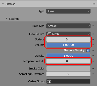
Setup the smoke to emit from the volume, rather than the surface - this is to ensure the smoke fills the entire volume. Also, set up the smoke with a temperature of 0.0 to prevent it drifting due to convection. You can also optionally configure the smoke domain to change the Field Weights to remove the effects of gravity, etc. - but this isn't strictly necessary.
Smoke Simulation
The add-on needs to be able to access the raw disk file from the simulation and for this it will need to know the location of the '.blend' file - so firstly you'll need to save your .blend file.
With the file now saved, you should be able to access the Cache details of the smoke domain. Leave the File Format as 'Point Cache' and give the cache a name by double-clicking the blank row in the list of caches (the add-on requires a name to be specified as this makes up the location of the file on disk). Since we're only capturing a volume, we don't need many frames in the simulation so set the Start frame to 0 and the End frame to 1.

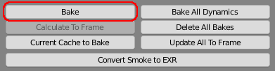
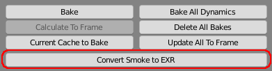
Click 'Bake' to bake the simulation to the cache files on disk.
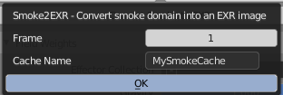
Once baked, click the 'Convert Smoke to EXR' button and fill in the details (CacheName should match the name you gave to your cache in the step above, Frame should be frame 1 when the volume should be filled with smoke). After a short delay you should have a number of images relating to your simulation, capturing your mesh into an EXR representing the volume.

Volumetric Material Nodes
To render the volume requires the 3-dimensional XYZ coordinates to be converted into 2-dimensional coordinates within the image. This is achieved by using the Z coordinate to determine which 'slice' of the image the point resides and then some fairly simple maths to location the point within that slice. By determining the point within the next adjacent 'slice' as well as the closest 'slice' we can mix between the two values to perform interpolation. A group node can be easily created using the Node Expressions add-on and the following text :
Code :
# Expression to convert Generated coordinates into 'sliced' coordinates for image generated from Smoke2EXR
# Use the Node Expressions add-on to generate the node group from this text
_x = Input[x]
_y = Input[y]
_z = Input[z]
_slice = min(1,max(_z,0)) * ZSlices{128}
_sliceNo1 = floor(_slice)
_sliceNo2 = _sliceNo1 + 1
_newx1 = (min(1,max(_x,0)) + _sliceNo1)/ZSlices
_newx2 = (min(1,max(_x,0)) + _sliceNo2)/ZSlices
Output1[] = combine(_newx1, 1-min(1,max(_y,0)), 0)
Output2[] = combine(_newx2, 1-min(1,max(_y,0)), 0)
# Choose interpolation mode... linear actually seems to produce less banding.
InterpolationMix = _slice - _sliceNo1
To use this, use the Text Editor in Blender to create a new text block named 'convertcoords' and paste the above text. In the Node Editor select Add/Maths Expression and enter the Expression as "TEXT:convertcoords". This should now create you a new Group Node with a Vector input named 'Input' and a Scalar input named ZSlices, with vector outputs named 'Output1' and 'Output2' and a scalar output for InterpolationMix.
Note that the number of slices (ZSlices) indicates how many 'layers' are in the volume - this will be dependent on the Domain dimensions and the resolution, with the resolution being for the 'longest' dimension of the domain; if the Z axis is the longest then there will be <resolution> slices, otherwise the number of slices can be calculated as <maxdimension>/<zdimension>*<resolution>, rounded down to an integer. If ZSlices is not set correctly the volume will not be rendered correctly.
You should set up the rest of your material as follows :

Note the two Image Texture nodes - both should be set to the same 'smoke' image generated from your smoke domain by the add-on. Ensure the Interpolation mode for each of the image nodes is not set to Linear (as Linear interpolation cannot cope with the tiled image format and will corrupt the volume).
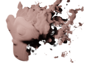
This should now produce a result similar to the following (if using Eevee you may need to adjust your Volume rendering settings for best quality) :

Significantly increase the Resolution of the smoke domain for greater detail and/or blur the edges of the cells by adding a little bit of dispersion to the smoke simulation before you capture the frame.
Further Steps
You may now manipulate the volume to add noise, distortion, etc. as desired. In the image below a variable noise (one of the Node Expressions presets) is increased based on the Y coordinate, using a higher smoke domain resolution to improve the detail over the previous examples (here I've used 256 rather than 128 - this does slow down the baking and conversion to EXR considerably).

The noise is added with the following nodes to use the Y coordinate to steadily increase the amound of noise added into the coordinates towards the back of Suzannes head.

The Maths nodes allow the amount of noise to be controlled (the Add offsets where the noise starts and the Multiple how fast the noise grows, with the Maximum preventing the noise being negative). The noise itself is generated within the node group which is generated from the expression :
Noise[] = vmult(vsub(noise(Input[], Scale), 0.5), Factor)
ie, take the Noise, subtract 0.5 from each of the channels (using the 'vector subtract' (vsub)) - to make the noise centred around zero, then multiple (using 'vector multiply' (vmult)) by the Factor. A Factor of zero will produce no noise, while increasing Factor will scale up the noise.
Tweaking the settings and varying an offset on the noise can produce interesting animated results :